• Skip to primary navigation
  • Skip to main content
  • FMECL Home
  • Research
    • Hypersonic Droplet Breakup
    • Multiphase Detonations
    • Shock-Driven Multiphase Instability
    • Ejecta Transport and Breakup
    • Astrophysical Hydrodynamics and Instabilities
    • Past Research Projects and Topics
  • People
  • Equipment
  • Codes
  • Publications
  • Contact Us

Fluid Mixing at Extreme Conditions Laboratory

FMECL

Texas A&M University College of Engineering

Facilities

Experimental Equipment

1. High-Speed Microscopy Shadowgraph

High-resolution imaging is achieved utilizing pulsed backlight illumination. The measurement volume is determined by both the focal plane and the depth of field of the imaging system. This method is versatile, being unaffected by the shape or material (whether transparent or opaque) of the particles, and enables the examination of sizes down to the micro-scale when coupled with a suitable optical system.

Equipment:

– Phantom T3610 with a K2 – Long Distance Microscope (1 million frames per second)

  • The backlit illumination utilizes a high-speed laser at 532 nm with a diffuser plate.
  • 120 kHz Ultrasonic Atomizer
https://fmecl.engr.tamu.edu/wp-content/uploads/sites/207/2024/02/Shodowgraph.mp4


  • Spray Characterization SUJ11
https://fmecl.engr.tamu.edu/wp-content/uploads/sites/207/2024/02/Airbast_Spray.mp4

– Specialized Imaging – SIMX16 with a K2 – Long Distance Microscope (1 billion frames per second)

  • The backlit illumination utilizes a Silux burst laser at 643 nm.
  • Monodisperse Dispenser 40 um – 15Khz
https://fmecl.engr.tamu.edu/wp-content/uploads/sites/207/2024/02/Monodisperse_SIMX16.mp4
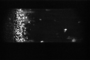
  • High magnification (x3.5) 170 um acetone droplet breakup.
https://fmecl.engr.tamu.edu/wp-content/uploads/sites/207/2024/02/Acetone_Droplet_Breakup.mp4

– Continuous 18 W Coherent Verdi C18 

https://fmecl.engr.tamu.edu/wp-content/uploads/sites/207/2024/02/Continuos_Laser2.mp4

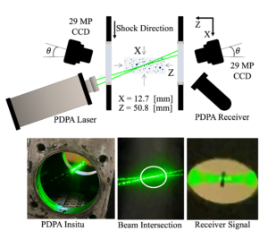
– Phase Doppler Particle Analyzer (PDPA) – (up to175 MHz)

The PDPA provides accurate and reliable flow velocity and particle size data at a low signal-to-noise ratio. It can detect particle diameter from 0.5 – 150 um.

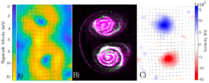
– Particle Imaging Velocimetry (PIV) and Planar Laser-Induced fluorescence (PLIF)

PIV imagery from TSI instruments 

  1. Full frame CCD Cameras (x2) 29 [MP] and APS-C frame (x1) 4[MP] with 5.5 [um] per pixel and QE of 50% at 510 [nm].
  2. NanoPIV 200 [mJ] at 532  [nm] and 40 [mJ] at 266 [nm].
  3. Custom Laser Sheet Forming Optics

– PIV imagery from LaVision 

  1. APS-C fImager CX-25 (x2) 25 [MP] with 2.7 [um] per pixel and QE of 70% at 510 [nm].
  2. NanoPIV 200 [mJ] at 532 [nm].
  3. Laser Sheet Forming Optics.

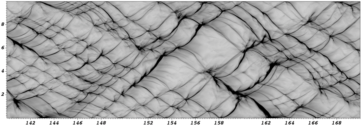
– Planar Laser Mie Scattering

High-resolution [29 MP] imaging of droplets interacting with shock and detonation waves.

FLASH Code

FLASH was originally developed by the University of Chicago under the auspices of the DOE/ASCI program and now maintained by the Flash Center for Computational Science (link) at the University of Rochester. FLASH is a multi-physics, finite-volume, Eulerian code whose capabilities include Adaptive Mesh Refinement (AMR) on a block-structured mesh; state-of-the-art hydrodynamics and magnetohydrodynamics solvers; implicit solvers for diffusion using the HYPRE library that include thermal conduction, radiation diffusion, resistivity, and viscosity; and a generic, highly scalable, parallel particles framework including Lagrangian tracer particles.It uses various split and unsplit hydrodynamic solvers including 5th order Weighted essentially non-oscillatory (WENO) methods and the piecewise parabolic method (PPM). FLASH is a professionally software-engineered code (Fortran based) with a wide user base and has been applied to a variety of astrophysics problems, high energy density physics experiments, and to fundamental problems such as combustion, fluid instabilities, and turbulence. FLASH is compiled efficiently with unique physics for each problem and is highly parallel scaling to 100K cores. The AMR capabilities and simple block-structured mesh make it a highly efficient code.

https://fmecl.engr.tamu.edu/wp-content/uploads/sites/207/2022/02/d10logn_wert_yfuel_rad.mp4

The Eulerian-Lagrangian particle-in-cell (PIC) method  was implemented in FLASH by our research group, and includes phase change and breakup for droplets. In this method particles are represented as meshless Lagrangian points which interact with the continuous phase represented on an Eulerian mesh. For computational efficiency, the Lagrangian points are virtual particles and can represent groups of particles (up to 1000s of particles per point). The discretized conservation equations in the split Piecewise Parabolic Method (PPM) solver are modified to include source terms for the mass, momentum, and energy to introduce the effect of active particles. The momentum source appears due to the drag force experienced by the particles, where the coefficient of drag is calculated using various drag models. The energy and mass source terms are found using various models including the Ranz-Marshall correlation and Spalding transfer model. Mass transfer significantly modifies the energy source term due to the latent heat of vaporization. Phase change properties are calculated from thermodynamic curve fits. A new species where the particle vapor phase is stored after evaporation is initialized with the mass transfer model. These models have been validated against analytical solutions and known values. Breakup models (for various breakup regimes) have also been implemented, and validated against past experimental work from our group. Various reaction models have also been implemented including a generic N-species, M-step framework for multistep models.Together with the breakup models, the code allows us to simulate complex reacting mutliphase flows.

Air/Decane Detonation cells

Simulation of a gaseous air/decane simulation using a 3-step, 7-species model in FLASH.

Hydrodynamics and Fluids Mixing Shock Tube

  • DRIVER & DRIVEN

The shock tube facility has a 5.5″ x 5.5″ internal area and can shock wave strengths up to Mach 2.75 into atmospheric pressure air. It has three main sections; the driver, the driven, and the test sections. The driver section is made of round tube with an 8″ internal diameter and 1 inch wall thickness. The driven and test sections are made of square tube with a wall thickness of 0.75 inches and an internal cross section of 5.5″ by 5.5″. The test section contains window ports that allow the visualization of the fluid dynamics occurring within the tube. It is made of several modular sections that can be rearranged to allow visualization of the fluid dynamics at different times after shock acceleration. The tube has a closed end, trapping the shock pressure within the tube, and creating a reflected shock wave that can be used to accelerate a fluid field for a second time. The end wall has a sapphire window port that allows a laser to illuminate the fluid flow.


Multiphase Detonation Tube

The multi-phase detonation facility  is designed to investigate detonations in liquid droplet and solid particulate fuels and gaseous oxidizer. The tube itself has a cross section of 2.25″ by 2.25″ (57mm x 57mm) and length of approx 3m and is designed to be capable of handling detonations of a variety of fuel-ox mixtures and initial pressures/temperatures. Its construction consists of an ignition/fill section, 500mm detonation-to-deflagration accelerator section, 1.5m of development section to measure the wave, pizeoelectric transducers to measure pressure/velocity profiles, two test sections with optical through access, and a hydraulically clamped diaphragm loader and expansion/blowdown tank to contain the detonation. The facility has full optical access to directly image the multiphase flow field and reacting fuel droplets and particles via the various method in use in the lab (Laser-illuminated imagery, LIF,PLIF, PDPA particle and droplet sizer, Schlieren, shadowgraphy, Pyrometry, etc.), as well as pressure and temperature diagnostics.

Multiphase Detonation Tube

The multiphase detonation tube facility.


© 2016–2026 Fluid Mixing at Extreme Conditions Laboratory Log in

Texas A&M Engineering Experiment Station Logo
  • College of Engineering
  • Facebook
  • Twitter
  • State of Texas
  • Open Records
  • Risk, Fraud & Misconduct Hotline
  • Statewide Search
  • Site Links & Policies
  • Accommodations
  • Environmental Health, Safety & Security
  • Employment